Hydro Boost Install Diagram
With slotted 3/8 mounting holes for easy installation. Hydroboost Braking System Hydro boost Power. A hydroboost system uses hydraulic pressure to assist in pushing the plunger in the brake cylinder when you step on the pedal. The hydroboost unit simply replaces the vacuum booster and fits between the firewall and the brake master cylinder.

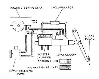
Proper diagnosis of hydro-boost related problems requires an understanding of how the system works. A typical hydro-boost is shown in Figure 1. The hydro-boost is plumbed in line with the steering gear. The power steering pump supplies pressurized fluid for both the power steering gear and hydro-boost. Spool Valve Fluid flow in and out of the hydro-boost is controlled by what is known as a spool valve. Grecheskij shrift russkij. Spool valves are used in a variety of hydraulic components, such as the valve body of an automatic transmission.
A spool valve is basically a hollow cylinder with a number of rings machined into it (see Figure 2). The surface of the spool valve is highly polished to form a sealing surface. The raised portions of the cylinder are called lands while the indentations are called annular grooves. Figure 3 shows a simplified spool valve positioned in a bore with three ports.
The path of the pressurized fluid from port 1 is determined by the position of the spool valve. The spool valve is positioned in figure 4 to allow fluid flow from port 1 to port 2 while port 3 is blocked by land #1. Figure 4 shows the spool valve moved to the left which changes the fluid flow. The fluid flow is now from port 1 to port 3 with port 2 being blocked by land #2. The spool valve in a hydro-boost works in a similar fashion.
Hydro-boost Construction Figure 5 shows a cutaway of a hydro-boost with all the major components labeled. These include the housing, power chamber, input rod assembly, a lever assembly, a power piston, spool valve assembly and an output rod. The housing is fitted with three ports as identified in Figure 6. The spool valve fits into a precisely machined bore that is part of the hydro-boost housing as shown in Figure 7. The fit between the spool valve and the bore is such that it creates a seal while at the same time allowing enough fluid between the lands and bore to provide lubrication. The spool valve’s position is determined by the lever assembly which is connected to the input rod. Pedal Unapplied When the brakes are unapplied the spool valve is positioned as shown in Figure 8.
In this position the pressurized fluid from the power steering pump is allowed to flow to the steering gear, but not into the power chamber. The spool valve vents the power chamber to the return line of the power steering pump reservoir. Pedal Applied Once the brake is applied, the input rod moves forward (left) to the power piston assembly.